Electricity, Circuitry & Soldering
Key Concepts of Electricity and Circuit Breadboarding
In this exercise, you will gain a deeper understanding of key electricity concepts and practical experience in circuit breadboarding. By building and testing electrical circuits, you will enhance your problem-solving skills and ability to troubleshoot real-world electrical systems. This hands-on approach will solidify your theoretical knowledge and prepare you for more advanced applications.
Activity Resources:
Circuit Challenge Gauntlet
Make each of the following circuits and record any observations made.
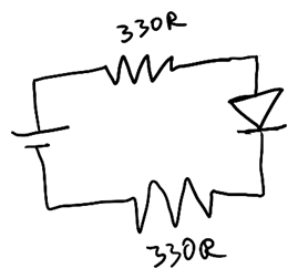
Circuit #1
Use a red led initially and measure the voltage before and after the led (black lead of DMM on the ground connection of the battery pack). Then swap to yellow and do the same. Repeat for green, blue, and white LED. (don’t use the one with 4 leads).
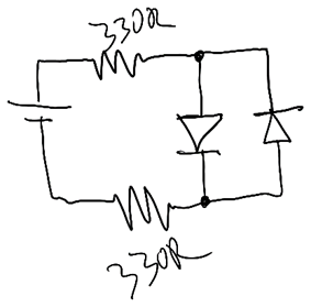
Circuit #2
Reverse the battery leads and see what happens. Why does this happen?
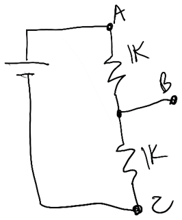
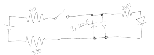
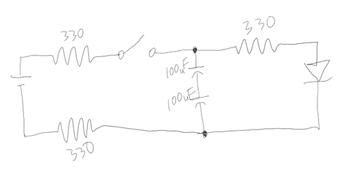
Circuit #3
Measure the voltage at A and B (black lead on C). Change the first resistor to 10K, what happens? Then swap the first and second resistors; what happens?
Circuit #4
Wire up the button from the kit into the circuit. Note the button has 4 leads, use the connection tester on your DMM to find which of the button’s leads are connected only when the button is pushed. When implemented in the circuit how quickly does the LED illuminate when the button is pressed?

Circuit #5
Change the connections with the button to the following. How does this modify the function of the button within the circuit?

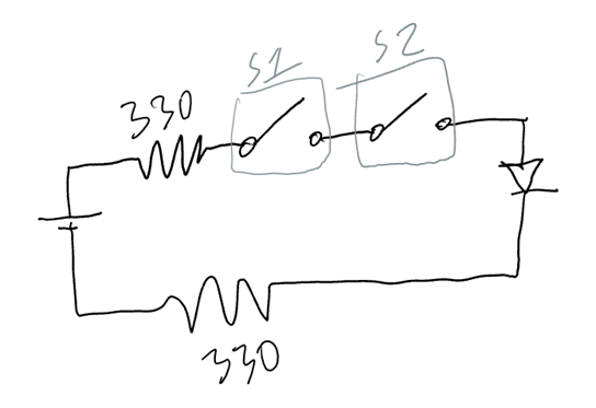
Circuit #6
Modify the circuit to now have two buttons’ as shown. Map out the states of the button (pressed or not) and what the state of the LED (lit or unlit) will be in each combination of options.
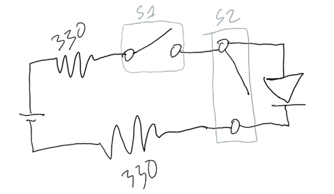
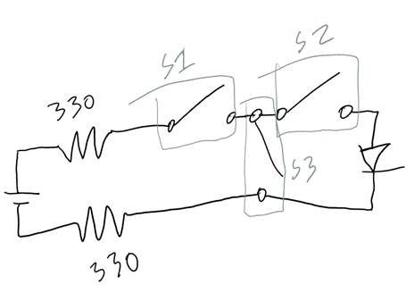
Circuit #7
Change the circuit to the following. Map out the new relationship between the buttons’ states and state of the LED.
Circuit #8
Change the circuit to the following. Map out the new relationship between the buttons’ states and state of the LED.
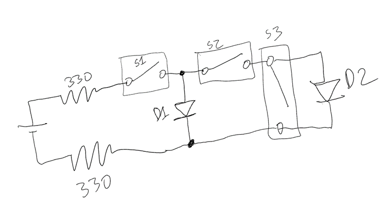
Circuit #9
Change the circuit to the following. Map out the new relationship between the buttons’ states and state of the LEDs.
Circuit #10
Create the following circuit. What is the behavior of the LED now when the button is pressed? What is the behavior as it is released? Is it the same as circuit #4 or different?
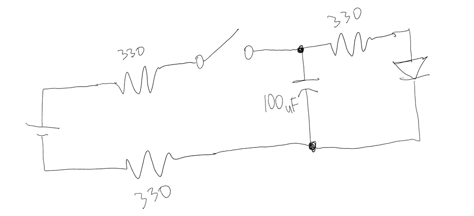
Circuit #11
Change the circuit to the following, how does this change the response of the LED?
Circuit #12
Change the circuit to the following, how does this change the response of the LED?
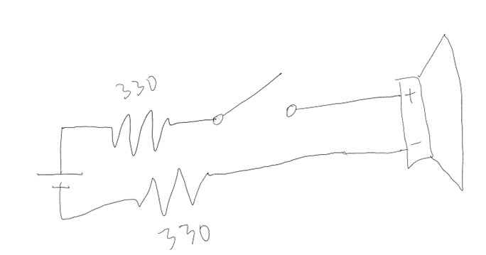
Circuit #13
Create the following circuit with the passive buzzer (one with the tape over it in the kit). Note the similarities to function with compared to the LED.
Modify this circuit to contain an LED that illuminates when the buzzer is buzzing as well as an LED that illuminates when the buzzer is not sounding. Write out your logic for the circuit you create and draw out the schematic.
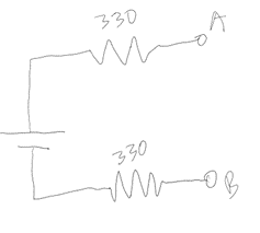
Circuit #14
Starting with this circuit and only making a connection from points A and B onward, draw out the schematic for a circuit that has two LEDs, each controlled by their own button. Try to do this without adding any more resistors.
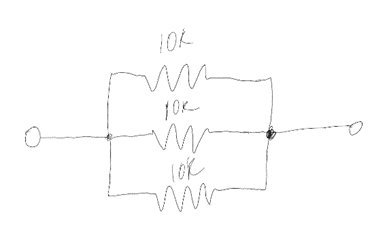
Circuit #15
Make the following circuit and measure its resistance across the two ends using your multimeter. Calculate the resistance that it should be and compare the two values.

Circuit #16
If Circuit #15 was modified to be hooked up to your battery voltage source, what would be the expected current flowing through the circuit.
Measure the voltage of the battery in DC mode on the multimeter and calculate the current. Then hooks up the circuit and measure it by using the multimeter in current mode (you will need to use the multimeter in series with the circuit to measure this, ask for help if this is confusing.
Circuit #17
Draw a circuit using parallel and/or series resistors that would make a total resistance of 2.5kilo ohms. Build and verify your circuit provides this resistance.
Try to make at least two unique circuits that accomplish this.
References:
Fundamental Techniques of Soldering
In this exercise, you will gain fundamental techniques of soldering, with a focus on proper safety procedures and hands-on practice to reinforce your skills in circuit assembly. You will learn to create reliable electrical connections, essential for building and maintaining electronic devices. This practical experience will prepare you for more complex projects and enhance your technical proficiency.
Activity Resources:
References: